Carbon steel pipelines are built by lining up six-, twelve-, or eighteen-meter long pipes one after another. At these lengths, the pipes are processed and coated in the shop. These inner and outer coatings serve to protect the piping from corrosion, and are specified by the engineer depending on the project requirements. The coated pipes are then sent into the field to build out the pipeline. On site, the pipes are welded together one after another, but the heat can burn and destroy the inner and outer coatings done by the manufacturer. The outer coating can be repaired during assembly, but not the inner coating. Attempts to repair the inner coating never turn out well, and the quality will be far inferior to that of the original factory coating. These areas are the weak spot on the pipeline, because they are exposed to premature corrosion, where the rate and speed of corrosion will depending on the nature of the fluid running through the piping. As such, a 120-kilometer long pipeline built with twelve-meter long pipes will have 10,000 non-conformities or critical points susceptible to failure from corrosion. When it comes to losses due to corrosion, there are both direct and indirect costs involved. The direct costs are related to the costs of repairing the line itself, while the indirect come from shrinkage or production losses as a result of downtime during repairs, not to mention other costs, like environmental costs. Depending on the magnitude or location of the failure, the indirect cost can climb to many times higher than the direct cost. Figures on this type of damage are so high they go beyond the realm of the rational. It is impossible to quantify this type of damage around the world. Studies on losses due to pipeline damage indicate that of all of the factors or causes underlying failures, approximately 55% are due to internal corrosion (National Association of Corrosion Engineers Report, NACE – 2012). With that said, a traditional pipe welding system leads to critical corrosion centers running from the start of the pipeline and throughout the entire length. The SIDGMAN® Coupling not only does away with these hot spots, but also strengthens the joint zone, furnishing construction and operational advantages for the pipelines, and bringing the risk of failure from internal corrosion in the welded joint areas practically down to zero.
Sidgman Welded COUPLING
Protect your investment controlling corrosion
The SIDGMAN® Coupling is an innovative welded pipe joint design that will significantly boost the lifetime of your line, ensuring reliable operation. It does not require maintenance, and the welding joint areas will no longer be the weak point they would be with the traditional welding system used to assemble and build pipelines.
- GENERAL
- VIDEOS
- DESIGN, DESCRIPTION, AND INSTALLATION
- WELDING HEAT TEST
- CORROSION TEST
- PRESSURE TEST
- BENEFITS
- COMPARISON TABLE
- VALIDATION
1.- GENERAL
Carbon steel pipelines are built by lining up six-, twelve-, or eighteen-meter long pipes one after another. At these lengths, the pipes are processed and coated in the shop. These inner and outer coatings serve to protect the piping from corrosion, and are specified by the engineer depending on the project requirements. The coated pipes are then sent into the field to build out the pipeline. On site, the pipes are welded together one after another, but the heat can burn and destroy the inner and outer coatings done by the manufacturer. The outer coating can be repaired during assembly, but not the inner coating. Attempts to repair the inner coating never turn out well, and the quality will be far inferior to that of the original factory coating. These areas are the weak spot on the pipeline, because they are exposed to premature corrosion, where the rate and speed of corrosion will depending on the nature of the fluid running through the piping. As such, a 120-kilometer long pipeline built with twelve-meter long pipes will have 10,000 non-conformities or critical points susceptible to failure from corrosion. When it comes to losses due to corrosion, there are both direct and indirect costs involved. The direct costs are related to the costs of repairing the line itself, while the indirect come from shrinkage or production losses as a result of downtime during repairs, not to mention other costs, like environmental costs. Depending on the magnitude or location of the failure, the indirect cost can climb to many times higher than the direct cost. Figures on this type of damage are so high they go beyond the realm of the rational. It is impossible to quantify this type of damage around the world. Studies on losses due to pipeline damage indicate that of all of the factors or causes underlying failures, approximately 55% are due to internal corrosion (National Association of Corrosion Engineers Report, NACE – 2012). With that said, a traditional pipe welding system leads to critical corrosion centers running from the start of the pipeline and throughout the entire length. The SIDGMAN® Coupling not only does away with these hot spots, but also strengthens the joint zone, furnishing construction and operational advantages for the pipelines, and bringing the risk of failure from internal corrosion in the welded joint areas practically down to zero.
2.- VIDEOS
Heat Exposure Test of the Weld
Assembly Procedure and Pressure Test
Corrosion Control
Assembly and Construction
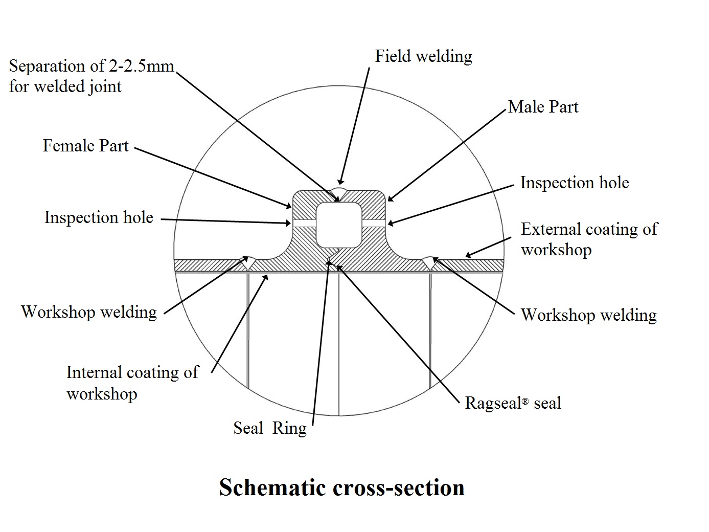
3.- DESIGN, DESCRIPTION, AND INSTALLATION
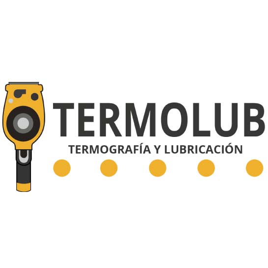
The SIDGMAN® Coupling is a two-piece system—one male and one female—welded in the shop to the ends of each pipe, so that they end up as the pipe facings. As the two parts are welded, any slag, blobs, or uneven sections of the welding are mechanically removed.
The male and female pieces should be welded to the pipes once the pipes meet the internal and external coatings already installed, with their unlined ends a minimum of 3” wide.
For each project, ASICORP will define the work methodology and the QA/QC for the activities of preparing the pipes, welding system and the final coating of both installed parts.
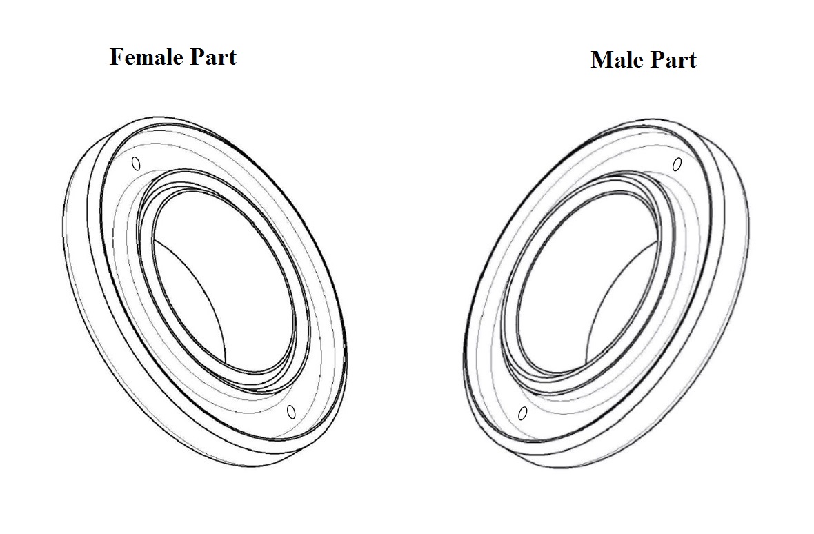
Now that the job in the shop is done, the pipes are sent out into the field where they will be lined up one after another so that the male facing of one pipe is up against the female facing of the next.
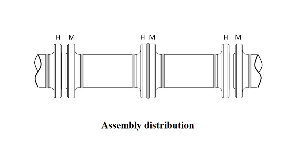
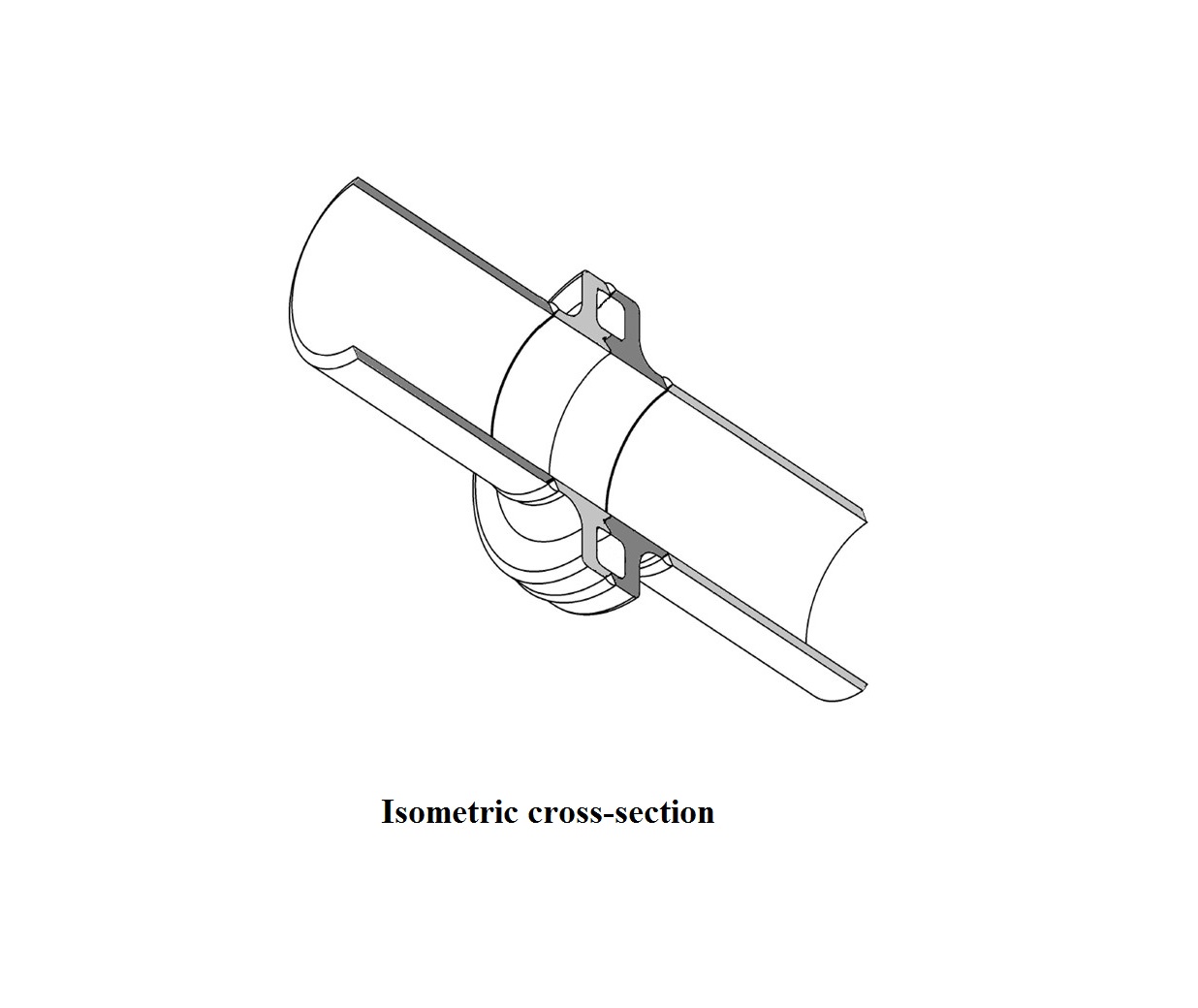
With the pipes lined up, the faces are assembled and tightened to squeeze the C'Ring and create a gap measuring 2.3 +/- 0.2mm., which is where the terminals are welded on the external bezels Finally, the rubber stoppers are placed into the holes of each part and the system is ready to be put into the trench. The way in which the two pieces are assembled creates an air chamber that prevents the flame and heat of the welding from impacting or burning the inner coating, as most of the heat dissipates through the device without ever touching the walls of the pipe. The C'Ring prevents the fluid running through the pipeline from entering the air chamber, making the systemic hermetically sealed.
4.- WELDING HEAT TESTS
To demonstrate how the Sidgman Coupling performs under the heat of welding as compared to a traditional pipe welding system, a comparative test was conducted. A painted pipe was cut lengthwise to make two half-rounds. Eight-inch diameter Schedule 40 pipes were used, and all of the half-rounds were painted on both faces with the same pattern, leaving a width of 20 millimeters free of paint in the area to weld. The test was run in parallel with the MIG welding system, two professional 6G welders, and welding equipment from the same make and model. The result with the traditional welding system showed signs that the paint had burned, with immediate combustion and a flame. By contrast, with the Sidgman Coupling, thanks to its special design, the paint was not damaged at all and remained intact. In the traditional system, the harm done to the inner coating is total and irreversible in the area close to the welded joint, a residue from the combustion is deposited as a result of the carbonization of the resin. But with the Sidgman Coupling, neither the inner coating nor the C'Ring is damaged or altered at all. The outer zone on the welded half-rounds revealed that with the traditional system, the heat from the welding destroyed the coating up to a distance of 40 millimeters on each side of the joint, with black residue from the combustion deposited there. By contrast again, with the Sidgman Coupling, the adjacent coating up to a width of 20 millimeters was not harmed at all and kept its original properties. The UNIQUE CHARACTERISTICS resulting from the Sidgman Coupling's geometry and innovative design ensure optimal results, saving on time and costs DURING CONSTRUCTION and providing SUBSTANTIAL OPERATIONAL BENEFITS....

Traditional welding system.

SIDGMAN® Coupling welding system.
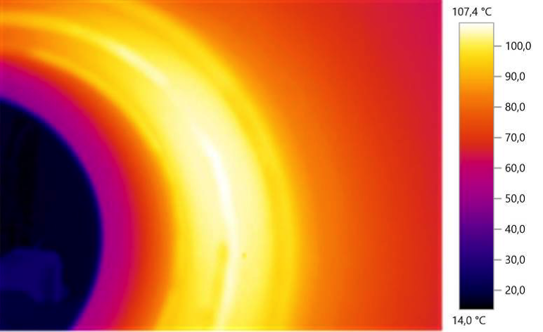
Thermography results. Maximum temperature reached during the Sidgman® Coupling welding process = 107.4°C.
5.- CORROSION TEST
A 1,200-hour corrosion test was done on both of the welded joint systems in a salt spray mist chamber and a condensation chamber, divided into four 300-hour cycles each, with 200 hours in the salt spray and 100 hours in condensation. This test was run in IDIC labs, and the evaluation was performed pursuant to the ASTM D-610.08 standard, which uses a scale from 0 to 10, where 10 is excellent behavior, with no sign of corrosion, and 0 is very deficient behavior, with more than 50% corrosion. With the 1,200 testing hours complete, the SIDGMAN® Coupling earned a score of 10, which is to say, no signs of corrosion, while the traditionally-welded piping scored a 0, meaning very high corrosion, the worst score the standard has (see graph).
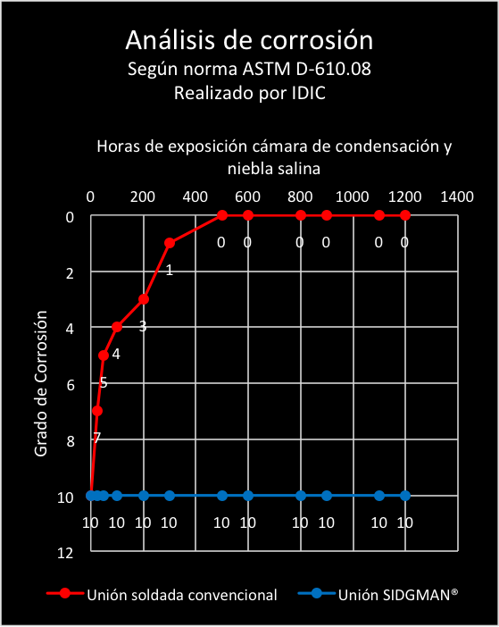
Comparison of corrosion between the traditionally-welded joint and the SIDGMAN Coupling.
With the test complete, the SIDGMAN® Coupling remained intact, with no change to the original properties of adherence, shine, and color.
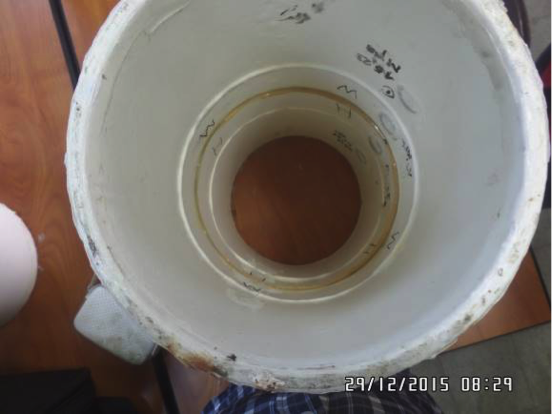
The SIDGMAN® Coupling after 1,200 hours of exposure in the corrosion test. No stains or signs of oxidation. At the end of the test, the paint remains unaltered on the entire part, with the original properties from the original coating intact.
On the other side, the traditionally-welded system showed signs of pitting and cracking, and had lost a thickness of 0.6 millimeters in the heat-affected zone, equivalent to 7% of the nominal at the end of the 1,200 testing hours.
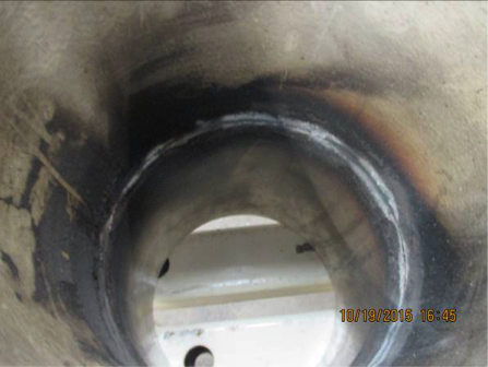
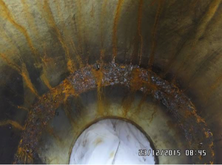
Sample of a pipe welded with the traditional system. Left: Before beginning the test, the welded joint with carbonized coating. Right: After 1,200 hours of corrosion testing, the inner metal wall in the welded joint area shows widespread corrosion, loss of wall thickness, and formation of pitting and cracking in the heat-affected zone.
Conclusions from the Corrosion Test. Given that advanced corrosion resulted in the welded area of the traditional joint in just two months of exposure, the estimate is that after five years, the corrosion in the welded joint zone could affect as much as 50% of the original thickness (8.18 millimeters), as the corrosion rate would depend on the type of fluid running through the piping. The traditionally-welded joint showed signs of cracks (low relief), derived from damage due to corrosion in the heat-affected zone. Unlike in the traditional welding system, which after just 24 hours of testing already showed significant signs of corrosion, the SIDGMAN® Coupling passed this demanding test with flying colors, showing no signs of corrosion at all. Because the internal coating with the SIDGMAN® Coupling will not require any repair and will remain original along the entire line, the piping will not be exposed to corrosion at the joins as it would be with the traditional welding model. The main conclusion from the test is that the life expectancy will be significantly longer with the SIDGMAN® Coupling.
6.- PRESSURE TESTS
From a mechanical standpoint, the structural characteristics and pressure resistance offered by the SIDGMAN® Coupling have been validated under the standards ASME VIII, ASME B16.5, and ASME B31.4, which govern the calculation, design, properties, and quality of materials used in fluid conveyance lines. The ASME VIII Division 2 standard covers design and structural requirements for any element of any system conveying pressurized fluids. Standard ASME B16.5, for couplings, classifies these elements into categories pursuant to the pressure demands to which they will be subject. This latter standard specifies classes 150 (300psi), 300 (750psi), 400 (1000psi) 600 (1500psi), 900 (2250psi), 1500 (3750psi), and 2500 (6250psi). The SIDGMAN® Coupling can be manufactured in any type of steel for any type of pressure. The choice will depend on the steel used in the piping and the requirements of the project. Because fluid conveyance lines exhibit hydraulic, chemical, mechanical, and trace differences, the SIDGMAN® Coupling is tailor-made for each project. Furthermore, the SIDGMAN® Coupling design includes finite element modeling and physical pressure behavior tests. As an example of this methodology, below is the procedure used for an eight-inch-diameter Schedule 80 SIDGMAN® Coupling, made of ASTM A-694 carbon steel. In this condition, the SIDGMAN® Coupling was modeled for the 600 and 2500 classes at a testing pressure 50% higher than the pressure stipulated by the standard; in other words, 2,250psi for a class 600; and 9,000 psi for a class 2500. Both models passed the acceptance levels required by the ASME VIII Division 2 standard, as well as the design requirements contained in the design. Because of the very high pressure needed for the class 2500, the physical tests were only done for class 600 devices. For this class, a total of ten SIDGMAN® Couplings were manufactured. The final outcome was optimal for all ten devices. The SIDGMAN® Coupling manufacturing method and design guarantee reproducibility and traceability, enabling steady and uniform production for large-scale jobs. With that said, the following three pressure tests were performed: Pressure Test N°1. This test was certified by Bureau Veritas. It was only done with the Sidgman® Coupling, with the end cup on each side, and ten two-hour cycles at a pressure of 2,500 psi. Once the ten cycles were complete, there were no leaks or pressure drops.
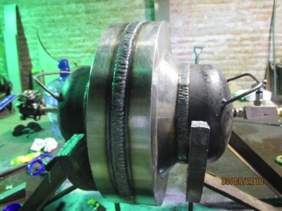
Welded SIDGMAN® Coupling resistance to pressure exposed to 2,500 psi for two hours.
Pressure Test N°2. Just as in Test N° 1, this test was also certified by Bureau Veritas. It was done with an 18-meter long line, composed of three six-meter pipes, each eight inches in diameter, Schedule 80, and two SIDGMAN® Couplings, testing at a pressure of 2,500psi for a total of ten two-hour cycles. With the test complete, the welded couplings displayed no leaks or pressure drops.
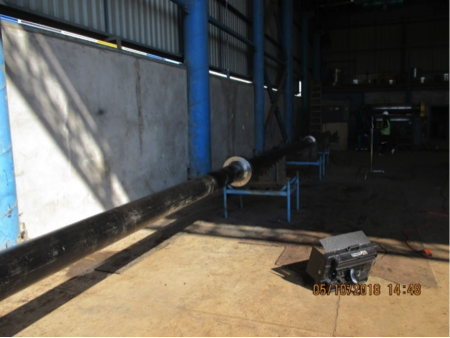
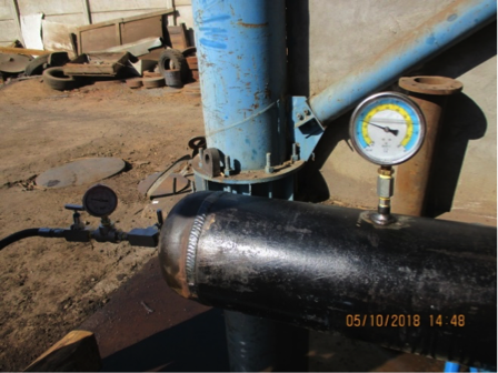
Line with two SIDGMAN® Welded Couplings and three six-meter long pipes. Pressure test = 2,500psi for two hours on an 18-meter line.
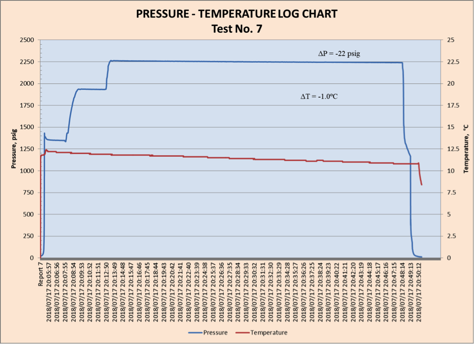
Pressure Test N°3. This third test was certified by an ASME expert, a known specialist in the field. It was run with the Dead Weight method, which requires equipment with a sensitivity of +/- 1psi. This equipment certifies the watertightness of the Sidgman Coupling, as it can detect even the smallest leak of working pressure. The test was done at a pressure 1.5 times higher than the pressure required in the class 600 standard, meaning 2,250psi. The final result was excellent. The SIDGMAN® Coupling passed the test and earned the certification from the ASME expert pursuant to the standard.
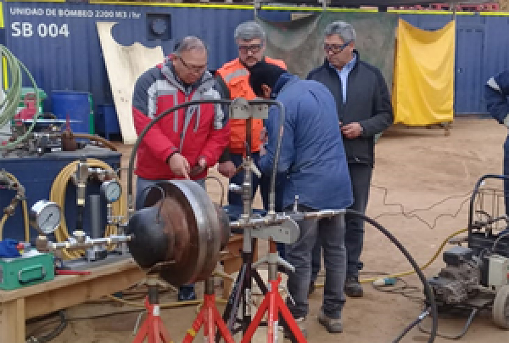
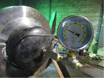
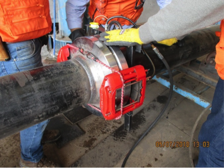
Preparing the Dead Weight equipment for the pressure test.
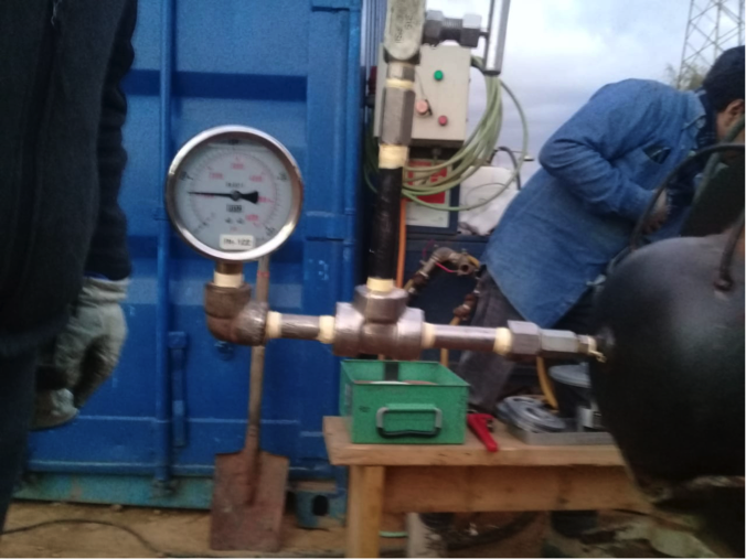
Recording the gradual rise in pressure during the test.
7.- BENEFITS OF THE SIDGMAN® COUPLING
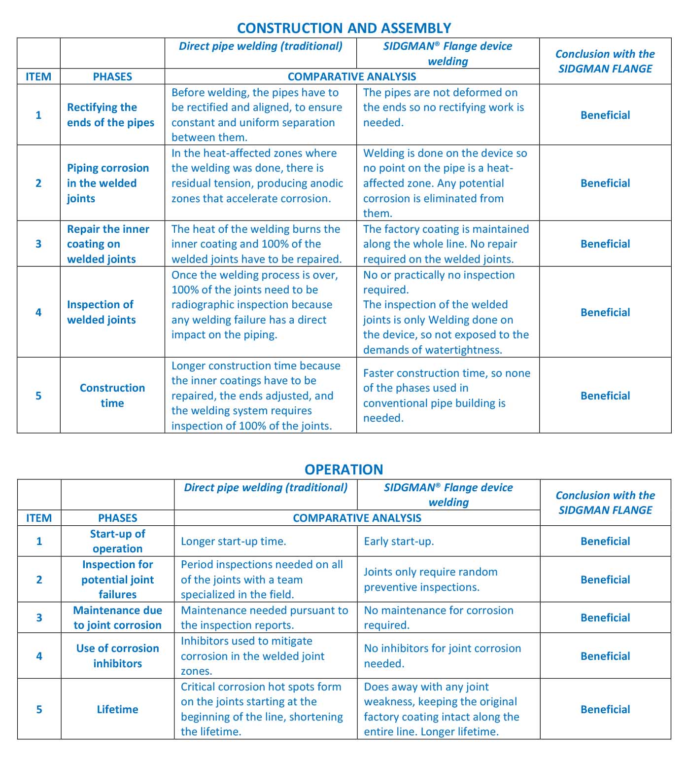
The SIDGMAN Coupling offers important benefits and advantages for fluid conveyance systems, from pipeline construction and assembly all the way up to final behavior during operation and the life expectancy. CONSTRUCTION AND ASSEMBLY BENEFITS When they are being transported to the field, pipes are often deformed, and they need braces placed on both ends to keep their shape. Likewise, to weld the pipes, they need to be aligned, concentric, and held in place with an appropriate gap; otherwise, work will be needed to make these adjustments. Another major issue that tends to happen when welding pipes with the traditional system is that the heat from the welding fully and irreversibly damages and burns the inner factory coating on the joint zone. When the SIDGMAN® Coupling is used to build pipelines, the heat from welding will not cause any harm to the inner coating, meaning it does not have to be repaired, leading to cost and time savings since these repairs are avoided. The SIDGMAN® Coupling is solid steel, so the facings keep their shape. No braces or machinery is needed to achieve pipe alignment and concentricity. The design contains a stopper to ensure precise spacing of 2 to 2.5 millimeters at the welding point on the outer rings of the male and female parts. To make assembly even easier, the system has a heel unit to easily fit together and move the parts. The tightening machine is part of the SIDGMAN® Coupling technology, with a pneumatic drive, and it is easily portable.
Easily portable pneumatic-drive machine to tighten the SIDGMAN® Coupling male-female system.
The central welding of the SIDGMAN® Coupling does not interact with the pipeline fluid and is therefore not exposed to hydrostatic pressure. It is only a structural union that does not require radiographic inspection. As a quality system for this central welding, it must be verified that the welding procedure defined for the project is met and, if a confirmation of the quality of the procedure is required, it is recommended to consider an ultrasonic inspection in a randomized manner. In short, assembling and building out pipelines with the SIDGMAN® Coupling requires less skilled labor and lower machinery costs, and avoids the tedious burden of repairing the inner factory coating. Moreover, the only quality assurance check required is a visual inspection of the welded joint. If you combine all of these savings and benefits, the SIDGMAN® Coupling can cut down on construction and assembly time by 30% or more compared to the traditional system. BENEFITS FOR CORROSIVE FLUIDS Fluid conveyance lines are exposed to corrosion in places where the coating fails, but if the coating is not porous and is firmly adhered to the pipe, there will be no failures or problems derived from corrosion. On the outside of the piping, where there are coating defects, corrosion can still be controlled with a cathodic protection. Nevertheless, on the inside, it is not possible to use cathodic protection, so the metal is exposed to corrosion in places where the coating has defects. The speed or rate of corrosion will vary depending on the nature of the fluids in the pipe. There may also be electrochemical or bacterial corrosion. When the pipeline is being put together, in the traditional system, the heat from the welding on the joints causes damage and combustion against the internal coating, leaving the metal bare and exposed to premature corrosion from the start. This weakness in the system makes the operation vulnerable to potentially unplanned failures. Any welded joint has heat-affected zones for a distance of up to 25 mm from the welding line. These zones are anodic centers where electrochemical corrosion happens even faster, and they stay within the pipeline. Unlike the traditional welding system, the SIDGMAN® Coupling is a welded joint system. Because the welding is done on the coupling, there are no heat-affected zones on the pipes themselves, so the coating retains its original design properties along the entire line. In short, the SIDGMAN® Coupling meets all of these needs. That means, it does not harm the inner coating, it does not form any heat-affected zones on the pipes, it prevents the pipeline from exposure to corrosion in the joint zones, and not only does it not weaken the line, it actually mechanically strengthens it. OPERATIONAL BENEFITS Pipelines are like arteries that feed into a given process. If the fluid they carry stops flowing, the process comes to a halt, undermining production. Without water, there is no copper. If the tailings cannot be adequately disposed of, production shuts down. When the concentrate does not arrive, the product cannot be delivered. In other words, pipelines need to be reliably up and running around the clock Anything that makes it easier to build pipelines that will keep the operation running continuously, without any shutdowns or breaks, will have a positive impact on business profitability Many fluid conveyance lines generate high operational costs due to different types of failures, which then lead to shutdowns while repairs are being done. In pipelines where these failures happen periodically, companies need to have contracts in place and permanent support staff to do preventive inspections and/or maintenance. Due to corrosion issues on the welded joints, fluid conveyance lines frequently need to use inhibitors to counteract the corrosive effect. But with the SIDGMAN® Coupling, that will not be necessary, meaning that all of the costs and inconveniences these additives cause during the operation go away. In summary The SIDGMAN® Coupling guarantees high operational reliability; It requires little or no maintenance; Due to its design characteristics, unique and special, it ensures cost savings in the operation and offers a significantly longer operational lifetime with respect to the current fluid transport lines.
8.- CAMPARISON TABLE
9.- VALIDATION

CORFO PROJECTS
Innovation. Development of Prototype
Validation and Packaging
CODIGO
15ITE1-39748
16ITE2- 64172
VALIDATION
VALIDATION OF HYDROSTATIC TEST COMPLIANCE Sidgman Coupling Unit Model 8 “ ANSI Class 600, was tested in accordance with the requirements of ASME B31.4, section 8
HYDROSTATIC TEST – DEAD WEIGHT TESTER with increments less than or equal to 1 psi
INSPECTION AND VERIFICATION OF PRESSURE TESTS, WELDING PROCESS AND INTERNAL PIPING COATING

FINITE ELEMENT ANALYSIS ASME VIII - DIVISION 2
HERMETICITY AND PRESSURE RESISTANCE INSPECTION
THERMOGRAPHIC INSPECTION